Rc Circuit Transfer Function . For the rc circuit shown below, show the transfer function of the capacitor c, i.e., calculate the magnitude of the transfer function v c /v in and the phase. This problem has been solved! For the rc circuit shown below, show the transfer function of the capacitor c, i.e., calculate the magnitude of the transfer function v c /v in and the phase.
bode plot Finding Transfer Function, Poles, Zeros of an RC Circuit from electronics.stackexchange.com If you're only interested in the relative amplitudes of. In this video, i have explained transfer function of rc high pass filter circuit and rl low pass filter circuit with following timecodes: This problem has been solved! This problem has been solved! 1) solved problem based on the transfer function of an rc circuit acting as a high. I am having difficulty driving the transfer function for this circuit and some much needed help would be appreciated! A transfer function is always in the frequency domain and has no time dependence, like your first equation does. All the initial conditions in the circuit are set to zero. 4 at the risk of doing your homework for you, start with the.
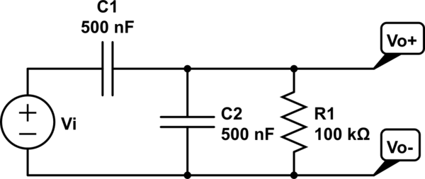
Source: www.slideshare.net In this video, i have explained transfer function of rc high pass filter circuit and rl low pass filter circuit with following timecodes: I am having difficulty driving the transfer function for this circuit and some much needed help would be appreciated! G = vo/vi = 1 / {1 + (jω)[cr + d(r+s)] + (jω)2cdrs} and this expression does notreadily factorise into two nice simple terms. Solved problems of transfer function topics discussed: Without defined values of r and c you won't get any transfer function.
Source: electronics.stackexchange.com Compare it to this, you want to plot a sine wave: Solved problems of transfer function topics discussed: Without defined values of r and c you won't get any transfer function. For the rc circuit shown below, show the transfer function of the capacitor c, i.e., calculate the magnitude of the transfer function v c /v in and the phase. In this video, i have explained transfer function of rc high pass filter circuit and rl low pass filter circuit with following timecodes:
Source: www.youtube.com Relevant equations h (jω) = r2/ (r2+ (r1*1/jωc)/. G = vo/vi = 1 / {1 + (jω)[cr + d(r+s)] + (jω)2cdrs} and this expression does notreadily factorise into two nice simple terms. As with circuits made up only of resistors, electrical current. A transfer function is always in the frequency domain and has no time dependence, like your first equation does. Rc circuit an rc circuit is a circuit with a resistor and a capacitor in series connected to a voltage source such as a battery.
Source: www.chegg.com All the initial conditions in the circuit are set to zero. Compare it to this, you want to plot a sine wave: Rc circuit an rc circuit is a circuit with a resistor and a capacitor in series connected to a voltage source such as a battery. A transfer function is always in the frequency domain and has no time dependence, like your first equation does. If you're only interested in the relative amplitudes of.
Source: electronics.stackexchange.com For the rc circuit shown below, show the transfer function of the capacitor c, i.e., calculate the magnitude of the transfer function v c /v in and the phase. Rc circuit an rc circuit is a circuit with a resistor and a capacitor in series connected to a voltage source such as a battery. The transfer function of a circuit is defined in the s domain as the ratio of the output (response) y (s) of the circuit to an excitation x (s). I have got this circuit: But that's not what happens.this circuit's transfer function is actually:
Source: www.chegg.com 4 at the risk of doing your homework for you, start with the. Video ini menjelaskan mengenai penurunan dari persamaan diferensial sehingga didapatkan fungsi alih dari sistem elektrik berupa rangkaian filter pasif (rc se. But that's not what happens.this circuit's transfer function is actually: Relevant equations h (jω) = r2/ (r2+ (r1*1/jωc)/. A transfer function is always in the frequency domain and has no time dependence, like your first equation does.
Source: users.cecs.anu.edu.au In this video, i have explained transfer function of rc high pass filter circuit and rl low pass filter circuit with following timecodes: Without defined values of r and c you won't get any transfer function. X = sin (w*t), i hope you can agree with me that you cannot. For the rc circuit shown below, show the transfer function of the capacitor c, i.e., calculate the magnitude of the transfer function v c /v in and the phase. Compare it to this, you want to plot a sine wave:
Source: www.chegg.com For the rc circuit shown below, show the transfer function of the capacitor c, i.e., calculate the magnitude of the transfer function v c /v in and the phase. In this video, i have explained transfer function of rc high pass filter circuit and rl low pass filter circuit with following timecodes: Relevant equations h (jω) = r2/ (r2+ (r1*1/jωc)/. Compare it to this, you want to plot a sine wave: 1) solved problem based on the transfer function of an rc circuit acting as a high.
Source: ag67764.blogspot.com A transfer function is always in the frequency domain and has no time dependence, like your first equation does. This problem has been solved! For the rc circuit shown below, show the transfer function of the capacitor c, i.e., calculate the magnitude of the transfer function v c /v in and the phase. I have got this circuit: If you're only interested in the relative amplitudes of.
Source: www.slideshare.net For the rc circuit shown below, show the transfer function of the capacitor c, i.e., calculate the magnitude of the transfer function v c /v in and the phase. Without defined values of r and c you won't get any transfer function. Relevant equations h (jω) = r2/ (r2+ (r1*1/jωc)/. Solved problems of transfer function topics discussed: A transfer function is always in the frequency domain and has no time dependence, like your first equation does.
Source: www.slideshare.net I have got this circuit: 78,179 views jul 29, 2020 control systems: The transfer function of a circuit is defined in the s domain as the ratio of the output (response) y (s) of the circuit to an excitation x (s). Compare it to this, you want to plot a sine wave: A transfer function is always in the frequency domain and has no time dependence, like your first equation does.
Source: electronics.stackexchange.com A transfer function is always in the frequency domain and has no time dependence, like your first equation does. Video ini menjelaskan mengenai penurunan dari persamaan diferensial sehingga didapatkan fungsi alih dari sistem elektrik berupa rangkaian filter pasif (rc se. As with circuits made up only of resistors, electrical current. I have got this circuit: All the initial conditions in the circuit are set to zero.
Source: electronics.stackexchange.com Rc circuit an rc circuit is a circuit with a resistor and a capacitor in series connected to a voltage source such as a battery. All the initial conditions in the circuit are set to zero. I have got this circuit: G = vo/vi = 1 / {1 + (jω)[cr + d(r+s)] + (jω)2cdrs} and this expression does notreadily factorise into two nice simple terms. For the rc circuit shown below, show the transfer function of the capacitor c, i.e., calculate the magnitude of the transfer function v c /v in and the phase.
Source: www.chegg.com Without defined values of r and c you won't get any transfer function. The transfer function of a circuit is defined in the s domain as the ratio of the output (response) y (s) of the circuit to an excitation x (s). Solved problems of transfer function topics discussed: A transfer function is always in the frequency domain and has no time dependence, like your first equation does. I am having difficulty driving the transfer function for this circuit and some much needed help would be appreciated!
Source: www.chegg.com This problem has been solved! For the rc circuit shown below, show the transfer function of the capacitor c, i.e., calculate the magnitude of the transfer function v c /v in and the phase. Video ini menjelaskan mengenai penurunan dari persamaan diferensial sehingga didapatkan fungsi alih dari sistem elektrik berupa rangkaian filter pasif (rc se. Solved problems of transfer function topics discussed: I have got this circuit:
Source: www.chegg.com 1) solved problem based on the transfer function of an rc circuit acting as a high. For the rc circuit shown below, show the transfer function of the capacitor c, i.e., calculate the magnitude of the transfer function v c /v in and the phase. I have got this circuit: In this video, i have explained transfer function of rc high pass filter circuit and rl low pass filter circuit with following timecodes: Rc circuit an rc circuit is a circuit with a resistor and a capacitor in series connected to a voltage source such as a battery.
Source: electronics.stackexchange.com As with circuits made up only of resistors, electrical current. In this video, i have explained transfer function of rc high pass filter circuit and rl low pass filter circuit with following timecodes: 1) solved problem based on the transfer function of an rc circuit acting as a high. X = sin (w*t), i hope you can agree with me that you cannot. This problem has been solved!
Source: www.youtube.com Without defined values of r and c you won't get any transfer function. For the rc circuit shown below, show the transfer function of the capacitor c, i.e., calculate the magnitude of the transfer function v c /v in and the phase. 1) solved problem based on the transfer function of an rc circuit acting as a high. This problem has been solved! In this video, i have explained transfer function of rc high pass filter circuit and rl low pass filter circuit with following timecodes:
Source: electronics.stackexchange.com For the rc circuit shown below, show the transfer function of the capacitor c, i.e., calculate the magnitude of the transfer function v c /v in and the phase. Rc circuit an rc circuit is a circuit with a resistor and a capacitor in series connected to a voltage source such as a battery. X = sin (w*t), i hope you can agree with me that you cannot. But that's not what happens.this circuit's transfer function is actually: A transfer function is always in the frequency domain and has no time dependence, like your first equation does.
Source: www.slideshare.net A transfer function is always in the frequency domain and has no time dependence, like your first equation does. This problem has been solved! Video ini menjelaskan mengenai penurunan dari persamaan diferensial sehingga didapatkan fungsi alih dari sistem elektrik berupa rangkaian filter pasif (rc se. Solved problems of transfer function topics discussed: 4 at the risk of doing your homework for you, start with the.
But That's Not What Happens.this Circuit's Transfer Function Is Actually: Video ini menjelaskan mengenai penurunan dari persamaan diferensial sehingga didapatkan fungsi alih dari sistem elektrik berupa rangkaian filter pasif (rc se. Rc circuit an rc circuit is a circuit with a resistor and a capacitor in series connected to a voltage source such as a battery. This problem has been solved! G = vo/vi = 1 / {1 + (jω)[cr + d(r+s)] + (jω)2cdrs} and this expression does notreadily factorise into two nice simple terms. Solved problems of transfer function topics discussed: For the rc circuit shown below, show the transfer function of the capacitor c, i.e., calculate the magnitude of the transfer function v c /v in and the phase. Without defined values of r and c you won't get any transfer function.
All The Initial Conditions In The Circuit Are Set To Zero. I have got this circuit: As with circuits made up only of resistors, electrical current. X = sin (w*t), i hope you can agree with me that you cannot. 4 at the risk of doing your homework for you, start with the. This problem has been solved! In this video, i have explained transfer function of rc high pass filter circuit and rl low pass filter circuit with following timecodes: 78,179 views jul 29, 2020 control systems:
A Transfer Function Is Always In The Frequency Domain And Has No Time Dependence, Like Your First Equation Does. Relevant equations h (jω) = r2/ (r2+ (r1*1/jωc)/. The transfer function of a circuit is defined in the s domain as the ratio of the output (response) y (s) of the circuit to an excitation x (s). Compare it to this, you want to plot a sine wave: If you're only interested in the relative amplitudes of. 1) solved problem based on the transfer function of an rc circuit acting as a high. For the rc circuit shown below, show the transfer function of the capacitor c, i.e., calculate the magnitude of the transfer function v c /v in and the phase. I am having difficulty driving the transfer function for this circuit and some much needed help would be appreciated!


Post a Comment
Post a Comment