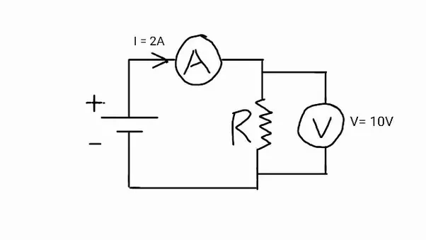
Circuit With Voltmeter And Ammeter. What are the expected readings of the ammeter and voltmeter for the circuit in the figure below? Learn about the instruments we use to measure voltage and current. Ammeter is always connected in series with the circuit.
A part of a circuit diagram shows the ammeter connected in series and from www.quora.com
Ammeter is connected in series with the circuit element whereas voltmeter is connected in parallel with the electrical circuit element. Voltmeter is always connected in parallel with the the circuit. Class 10 sciencea lot of students are confus. You can connect a voltmeter to a circuit without disconnecting it, unlike an ammeter: The ammeter is defined as the device used for measuring the small value current flows in the circuit, whereas the voltmeter measures the potential difference between any two points of. Voltmeter a voltmeter is a device which is used to measure voltage in an electric circuit. Using a voltmeter and using an ammeter is not the same. The following circuit represents the basic circuit diagram and the connection of the ammeter circuit in series and. It is connected in parallel across the points in the circuit.
Voltmeter A Voltmeter Is A Device Which Is Used To Measure Voltage In An Electric Circuit.
The following circuit represents the basic circuit diagram and the connection of the ammeter circuit in series and. Learn about the instruments we use to measure voltage and current. Ammeter is always connected in. Circuit with voltmeter and ammeter circuit with voltmeter and ammeter ac distribution panel, 120 volt, 8 positions, no meter, 8059. What are the expected readings of the ammeter and voltmeter for the circuit in the figure below? You can connect a voltmeter to a circuit without disconnecting it, unlike an ammeter: It is connected in parallel across the points in the circuit.
A Voltmeter Is Placed In Parallel With The Voltage Source To Receive Full Voltage And Must Have A Large Resistance To Limit Its Effect On The Circuit.
Using a voltmeter and using an ammeter is not the same. Voltmeter is always connected in parallel with the the circuit. This physics video tutorial provides a basic introduction into ammeters and voltmeters. How do we connect voltmeter and ammeter in an electric circuit class 10? Ammeters measure the electric current flowing in a circuit in amps a. Ammeter is connected in series with the circuit element whereas voltmeter is connected in parallel with the electrical circuit element. Why ammeter is connected in series and voltmeter in parallel?
In Lcr Circuit, If The Resistor, Inductor And Capacitor Is Connected In Series, Then The Voltmeter And Ammeter Readings Can Be Determined By Using The Current And Voltage Formula.
The ammeter is defined as the device used for measuring the small value current flows in the circuit, whereas the voltmeter measures the potential difference between any two points of. To measure the voltage across the points,. Class 10 sciencea lot of students are confus. A voltmeter is used to measure potential energy difference, voltage (in volts or. The construction of ammeter can be done in two ways like series and shunt. An ammeter is always connected in series with the circuit component you are measuring.a voltmeter is used to measure potential energy difference, voltage (in volts or. You can build a circuit yourself if you need to test it but don’t have a voltmeter.
The Voltmeter Carries Current Proportional To The Voltage Across The Circuit.
Created by david santopietro.watch the next lesson: Here is how to use a. 9 images about digital voltmeter circuit using ic l7107 : The voltmeter is connected across (parallel) the circuit and measures voltage across the circuit. An ammeter is always connected in series with the circuit component you are measuring.


Post a Comment
Post a Comment